Methodological recommendations for the course of descriptive geometry. Surface development
Picture 1
For the transition shown in rice. 1, given values are: hole diameter d, sides of the base a And b, height N.
Having drawn horizontal projections of the upper and lower bases, i.e. circle and rectangle, connect the vertices of the rectangle with points 0 and 3 of the circle, then construct a frontal projection of the transition.
The lateral surface of such a transition is a combined surface: it consists of four flat triangles marked on Fig.1, but in numbers I And II, and from four conical sections indicated by the number III. The vertices of these four equal conical surfaces lie at the vertices of the rectangle ( points s), and their bases coincide with the circle of the upper base of the transition.
On rice. 1, b the construction of the transition scan began with the construction of triangle I along the side b and height H1, equal to the segment s'ABOUT'(Fig. 1, a). Attached to it on both sides are developments of conical surfaces adjacent to it and tangent to it. III.
Natural lengths of the generatrices S 0 1 0 , S 0 2 0 , S 0 3 0 defined on rice. 1,a by the method of a right triangle and are respectively equal S 0 1 0, S 0 2 0, S 0 3 0. Side length l accepted equal to length chords of one division of the base. Further construction of the development is clear from the drawing.
The error when replacing an arc with a chord for the corresponding number of divisions will be for the angle α = 30º ~ 1%(with the number of divisions 3), and with the number of divisions equal to four ( α = 22.5º), ~ 0,56% . (Errors associated with the graphical construction of the scan are not taken into account here).
Analytical calculation
The natural lengths of the generators can be calculated using the formula

Formula 1
Where
- Lk - natural length of the corresponding generatrix;
- kα - the angle that determines the position of the projection of the generatrix;
- α = 180º/n when dividing half the base of a circle into n equal parts.
To do this, you need to first determine the value With.
From Figure 1, it is clear that:

Formula 2
Then, the divisions of the circle of the base of the transition must be numbered: put the number 0 at the horizontal projection of the largest generatrix and start counting the angles kα from it.
Size cos kα for the corresponding division can be determined from the table.


Figure 2
For its manufacture, in addition to dimensions H, d and a, you need to set the size e(displacement of the centers of the upper and lower bases). As in the previous case, connecting points s with points 0 And 3 circles, break lateral surface transition to four conical surfaces, indicated by numbers IV and V, and four triangles labeled I, II, III and tangents to conical surfaces.
The construction of the scan is similar to the previous one and is not shown in the drawing. The only difference is that the developments of the conical elements IV and V will in this case be unequal, and for triangles we will also have three different shapes.
Oblique transition from square to round cross-section

Figure 3
Lateral surface of transition to Fig.3 broken differently than the transitions shown in rice. 1 and 2. The midpoints of the sides of the base a and b (points s and s1) are connected to points 2 of the circle.
As a result of this construction, the lateral surface of the transition will consist of eight triangles I and II tangent to four conical surfaces III And IV. The construction of this development is clear from Fig.3, b. It is similar to the previous ones, but requires a larger number of constructions.
Based on materials:
“Technical development of sheet metal products” N.N. Vysotskaya 1968 “Mechanical Engineering”
The invention relates to metal forming and can be used in the manufacture of eccentric transitions between large-diameter pipes in the production of heat exchangers. A straight cone blank is obtained, from which a truncated eccentric cone blank is formed with bases of small and large diameters and a conical surface, one of the lines of which is perpendicular to the bases. The formation of a truncated eccentric cone blank is carried out by trimming the ends of a straight cone blank. An eccentric transition is obtained by flanging large and small diameters using a punch and a matrix. Moreover, for flanging a small diameter, the workpiece of a truncated eccentric cone is placed vertically with the small diameter upwards, the matrix is placed around the small diameter with its inner surface touching the outer surface of the workpiece at at least four points, the punch is advanced inside the small diameter of the workpiece parallel to the line on the conical surface perpendicular to the bases. For large-diameter flanging, a punch is used instead of a matrix and, accordingly, a matrix is used instead of a punch. Technological capabilities are expanding. 7 ill.
Drawings for RF patent 2492016


The invention relates to metal forming and can be used in the manufacture of eccentric transitions between large-diameter pipes in the production of heat exchangers.
There is a known method for manufacturing pipes in cold pipe rolling mills, according to which a pre-prepared initial hollow billet is fed along the rolling axis by a certain amount (feed amount) into the deformation zone and is compressed by rotating rolls with a variable radius of the stream while simultaneously moving the rolling stand (direct movement of the stand) in direction of supply of the workpiece (Technology and equipment of pipe production; tutorial for universities / V.Ya. Osadchiy, A.S. Vavilin, V.G. Zimovets, A.P. Kolikov. - M.: Intermetengineering, 2007. - pp. 448-452). In the final (extreme) position of the stand, the strands of the rolls form a caliber, the size of which ensures the free passage of the workpiece through it (the idle section of the longitudinal development of the strand profile). At this moment, the workpiece with the mandrel is rotated around its axis at a given angle (turned), after which the rolling stand moves in the opposite direction to its original position (reverse stroke of the stand) with simultaneous deformation of the workpiece section that was previously compressed during the forward stroke of the stand. Next, the workpiece is bent again and the above-described cycle of processing the workpiece on the mandrel is repeated many times until a finished pipe is obtained.
The described method of rolling pipes involves metal deformation using interchangeable tools and equipment in the form of gauges, gears and racks, made up of pairs of absolutely identical parts, which creates symmetry of the deformation process relative to the horizontal plane. In this process, the mandrel is self-aligned in the radial direction relative to the inner diameter of the pipe, which does not significantly reduce the value of the eccentric component of the wall difference and reduces the accuracy of cold-deformed pipes obtained by this method. In addition, high rolling forces, which require an increase in the mass of the deforming equipment and cause large elastic deformations of the stand, also lead to a decrease in the accuracy of the finished pipes, including those made of difficult-to-deform steels and alloys.
The closest to the proposed method is the method of manufacturing pipes with an eccentric transition by relative displacement of sections of a tubular blank with a conical transition, according to which a cylindrical section with a smaller diameter is rigidly fixed, and an internal support is created on a cylindrical section with a larger diameter, then it and the conical transition are sequentially bent relative to a cylindrical section with a smaller diameter (USSR Author's Certificate No. 806210, published 02/23/1981 - prototype).
The known method can only be applied to pipes of small diameter and does not allow the production of transitions of large diameter, i.e. diameter more than 1 m.
The problem is solved by the fact that in the method of manufacturing an eccentric transition, including obtaining a blank of a straight cone, forming from it a blank of a truncated eccentric cone with bases of small and large diameters and a conical surface, one of the lines of which is perpendicular to the bases, according to the invention, the formation of a blank of a truncated eccentric cone is carried out by cutting the ends of the workpiece of a straight cone, which is placed with a large diameter downwards, tilted until one line is taken on its conical surface in a vertical position, from the top point of which a horizontal line is drawn, along which the upper part of the workpiece of a straight cone is cut off, and its lower part is cut off along a horizontal line, drawn from the top point of the large base, raised when tilted, the eccentric transition is obtained by flanging large small diameters using a punch, and for flanging a small diameter, the workpiece of a truncated eccentric cone is placed vertically with the small diameter upward, the matrix is placed around the small diameter with its inner surface touching the outer surface of the workpiece at no less than four points, the punch is advanced inside the small diameter of the workpiece parallel to a line on the conical surface perpendicular to the bases, and for flanging of a large diameter, a punch is used instead of a matrix and, accordingly, a matrix is used instead of a punch.
The essence of the invention
In the field of mechanical engineering, and more precisely in the field of manufacturing heat exchangers, today there is the task of manufacturing eccentric transitions between large-diameter pipes with flanged ends. This task, as a rule, is either not performed or is performed using workaround technologies that damage the structure of the metal. Existing equipment is not adapted to solve these particular problems, and enterprises that have this equipment are often still forced to resort to workaround technologies when fulfilling orders.
The proposed invention solves the problem of manufacturing an eccentric transition of large diameter.
A general view of the eccentric transition is shown in Fig. 1. In Fig.1, d is the small diameter of the transition, D is the larger diameter of the transition, I is the length of the cylindrical part of the transition of small diameter, L is the length of the cylindrical part of the transition of a larger diameter, S is the thickness of the transition wall, H is the length of the transition.
When manufacturing an eccentric transition, a reamer is made, from which a blank for the future transition is subsequently produced by sharp welding and shaping.
The workpiece is bent using a 3-roll machine. Figure 2 shows a diagram of the bending of the transition blank on a three-roll machine: 1 - transition blank, 2 - ends of the blank, 3 - rolls. After bending, the workpiece is butt welded at the ends 3. A straight cone of the workpiece is obtained. Next, begin trimming the ends of the workpiece. For ease of marking when cutting the ends of a straight cone, self-aligning construction laser levels are used to mark the vertical and horizontal planes simultaneously. Figure 3 shows the marking diagram: 4 - self-aligning construction laser levels, 5 - vertical planes, 6 - horizontal planes, 7 - cone generatrix. A straight cone 8 is placed with a large diameter at the bottom. The straight cone is tilted so that one line on the surface of the cone 8 takes a vertical position in the vertical plane. From the top point “A” of the vertical line, draw a horizontal line 9. Along this line, cut off the upper part of the cone 8. From the top point “B” on the larger diameter of the cone 8, which turns out to be raised when tilted, draw a horizontal line 10. Along this line, cut off the lower part cone 8. An eccentric cone 11 is obtained. Thus, an eccentric cone blank is made from a simple truncated cone, taking into account allowances by cutting off part of a straight cone. As a result, we obtain a flattened workpiece of the eccentric transition.
Prepare the matrix and punch for each end of the transition based on the thickness of the matrix and punch of at least 5 sizes of the cylindrical part of the transition I and L. For a small diameter of the transition, the preparation diagram is shown in Fig. 4 and 5, for a larger diameter of the transition - in Fig. 6 and 7.
In Figs 4 and 5 the following are indicated: 11 - eccentric cone, 12 - matrix, 13 - stops, 14 - zones for removing weld reinforcement, 15 - punch, 16 - cup, 17 - press. The width of the matrix 12 and the punch 15 is assigned to at least 3 corresponding thicknesses of the transition wall S. The matrix 12 and the punch 15 are equipped with devices for carrying out lifting operations (not shown). For a small transition diameter d, the diameter of the punch 15 is selected as nominal with a tolerance of + for the tolerance for changes in the thickness of the transition metal, the diameter of the matrix 12 is calculated from the diameter of the punch, +2 wall thickness S, +2 tolerance for wall thickness, +1.5 mm. For a larger transition diameter D, the main one is the matrix, and the derivative is the punch (the matrix diameter is chosen at nominal value with a tolerance in - for the tolerance for changes in wall thickness, the punch diameter is calculated from the matrix diameter, - 2 wall thickness, - 2 tolerances for wall thickness, - 1, 5 mm). The roughness of the working surfaces of the punch and matrix is at least grade 11.
6 and 7 indicate: 11 - eccentric cone, 14 - zones for removing weld reinforcement, 17 - press, 18 - matrix, 19 - stops, 20 - punch, 21 - cup.
Prepare the equipment.
On the punch 15 for a small diameter and, accordingly, for a matrix with a larger diameter 18, after the radius of curvature of the inlet part there is a section with a slope of 20°±1°, the cylindrical part of the punch 15 or matrix 18 is at least half of their thickness. For a small diameter transition for the punch 15, a glass 16 is used for attachment to the press 17 with the possibility of removing the punch from the glass. The height of the cup 16 is calculated from the condition of the transition length H with tolerances + 3 punch thickness. For matrix 12, at least 3 stands are prepared with a height of 3 matrix thicknesses.
For a larger transition diameter, a glass 21 is prepared for the matrix and a stand for the punch 20 similarly to the above (Fig. 6).
A small diameter transition is flanged. To do this, the weld reinforcements in the stamping zone 14 are first removed (Fig. 4, Fig. 6). A matrix 12 is placed on a vertically mounted eccentric cone 11 with a small diameter upwards and installed in the working position, i.e. position of matrix 12 during stamping. The oval of small diameter is expanded in the area of the smaller axis, and the oval is adjusted to the circle. For expansion, a hydraulic set is used, for example, for straightening bodies with a maximum force of at least 3 tons and a set of extensions. Ensure that the inner surface of the matrix 12 and the outer surface of the eccentric cone 11 touch at least 4 points “B” (for flanging of a larger diameter “D”). Check the largest gap between the matrix 12 and the eccentric cone 11. This affects the size of the gap between the lower plane of the matrix and the welded stops. From below, under the matrix, 4 stops are welded to the eccentric cone diametrically in 2 perpendicular planes with a gap equal to the thickness of the transition wall + half the maximum gap (Fig. 4). For stamping, a press with a maximum force of at least 100 tons and a span height capable of placing a pre-assembled structure under the working cylinder is used. Under the working cylinder, a structure is assembled from a matrix 12 on supports and an eccentric cone 11 with a glass 16 inserted into it with an installed punch 15. The glass 16 is attached to the platform of the working cylinder of the press 17. Lubricant (graphite or a mixture) is applied to the punch 15 and the inner surface of the eccentric cone 11 graphite powder and industrial oil or a mixture of talc and liquid soap). Turn on the press 17, move the punch 15 inside the eccentric cone 11 parallel to the vertical plane 5. Upon completion of stamping, remove the punch 15 from the glass 16 and the eccentric cone 11 from the glass 16. Flanging of the small diameter is completed.
For flanging of a larger diameter, preparatory operations are performed similar to those for flanging of a small diameter, with a difference in the operations for the punch and the matrix (instead of the matrix - a punch and, accordingly, instead of a punch - a matrix) (Fig. 6). Subsequently, flanging of a larger diameter is performed (Fig. 7).
Example of concrete implementation
A transition with a flange of 1100-1600×12 mm is made. The flange size is 40 mm at both ends. According to Fig.1 d=1100 mm, D=1600 mm, I=L=40 mm, S=12 mm, r=R=20 mm, H=1500 mm.
The operations are performed according to Figs. 1-7. Get an eccentric transition with high quality surfaces.
Application of the proposed method will make it possible to perform an eccentric transition of a larger diameter.
CLAIM
A method for manufacturing an eccentric transition for connecting large-diameter pipes, including obtaining a straight cone blank, forming from it a truncated eccentric cone blank with bases of small and large diameters and a conical surface, one of the lines of which is perpendicular to the bases, characterized in that the formation of a truncated eccentric cone blank is carried out by cutting the ends of the straight cone workpiece, which is placed with a large diameter downwards, tilted until one line is taken on its conical surface in a vertical position, the upper part of the straight cone workpiece is cut off along a horizontal line drawn from the top point of the vertical line of the conical surface, and its lower part is cut off along the horizontal line drawn from the top point of the large base, raised when tilted, flanging of large and small diameters is carried out using a punch and a matrix, and for flanging a small diameter, a truncated eccentric cone blank is placed vertically with the small diameter upward, the matrix is placed around the small diameter touching its inner surface the outer surface of the workpiece at at least four points, the punch is advanced inside the small diameter of the workpiece parallel to a line on the conical surface perpendicular to the bases, and for flanging a large diameter, a punch is used instead of a matrix and, accordingly, instead of a punch, a matrix is used.
Federal Agency for Education
State educational institution
higher professional education
"Altai State Technical University them. I.I. Polzunov"
Biysk Technological Institute (branch)
G.I. Kunichan, L.I. Idt
CONSTRUCTION OF DECAYS
SURFACES
171200, 120100, 171500, 170600
UDC 515.0(075.8)
Kunichan G.I., Idt L.I. Construction of surface developments:
Methodological recommendations for the course of descriptive geometry for independent work of students of mechanical specialties 171200, 120100, 171500, 170600.
Alt. state tech. University, BTI. - Biysk.
Publishing house Alt. state tech. University, 2005. – 22 p.
The methodological recommendations discuss in detail examples of constructing developments of polyhedra and surfaces of revolution on the topic of constructing developments of surfaces for a course in descriptive geometry, which are presented in the form of lecture material. Methodological recommendations are offered for independent work full-time, evening and correspondence students.
Reviewed and approved
at the meeting
technical
Protocol No. 20 of 02/05/2004
Reviewer: Head of the Department of MRSiI BTI Altai State Technical University, Ph.D. Firsov A.M.
Kunichan G.I., Idt L.I., Leonova G.D., 2005
BTI AltSTU, 2005
GENERAL CONCEPTS ABOUT SURFACE DEVELOPMENT
Representing the surface in the form of a flexible but inextensible film, we can talk about such a transformation of the surface in which the surface is combined
with a plane without folds or tears. It should be noted that not every surface allows such a transformation. Below we will show what types of surfaces can be combined with a plane using bending, without stretching and compression.
Surfaces that allow such a transformation are called unfolding, and the figure on the plane into which the surface is transformed is called surface development.
The construction of surface developments is of great practical importance in the design of various products from sheet material. It should be noted that it is often necessary to make from sheet material not only developable surfaces, but also non-developable surfaces. In this case, the non-developable surface is divided into parts that can be approximately replaced by developable surfaces, and then developments of these parts are constructed.
Developable ruled surfaces include cylindrical, conical and tori.
All other curved surfaces do not develop onto a plane and therefore, if it is necessary to manufacture these surfaces from sheet material, they are approximately replaced by developable surfaces.
1 CONSTRUCTION OF PYRAMIDAL DECAYS
POVERKHNOSTEY
The construction of developments of pyramidal surfaces leads to the repeated construction of a natural type of triangles that make up a given pyramidal surface or a polyhedral surface, inscribed (or described) in some conical or ruled surface, which replaces the specified surface. The described method leads to the division of the surface into triangles, it is called using the triangle method(triangulation).
Let us show the application of this method for pyramidal surfaces. If we neglect graphic errors, then the constructed developments of such surfaces can be considered accurate.
Example 1. Construct a complete development of the surface of a part of a triangular pyramid SABC.
Since the side faces of the pyramid are triangles, to construct its development it is necessary to construct natural views of these triangles. To do this, the natural values of the side ribs must first be determined. The actual size of the side ribs can be determined using right triangles, in each of which one leg is the excess of the point S above the points A, IN And WITH, and the second leg is a segment equal to the horizontal projection of the corresponding lateral edge (Figure 1).
Since the sides of the lower base are horizontal, their natural values can be measured on a plane P 1 . After this, each side face is constructed as a triangle on three sides. The development of the lateral surface of the pyramid is obtained in the form of a series of triangles adjacent to one another with a common vertex S(S 2 C*, S 2 A*, S 2 B*– are the natural dimensions of the edges of the pyramid).
For applying points to the development D,E And F, corresponding to the vertices of the pyramid section by plane, you must first determine their natural distances from the vertex S D*,E* And F* to the corresponding natural sizes of the side ribs.
Picture 1
After constructing the development of the lateral surface of the truncated part of the pyramid, triangles should be attached to it ABC And DEF. Triangle ABC is the base of a truncated pyramid and is depicted on a horizontal projection plane in full size.
2 CONSTRUCTION OF CONICAL DRAWINGS
SURFACES
Let's consider the construction of developments of conical surfaces. Despite the fact that conical surfaces are developable and, therefore, have theoretically accurate developments, their approximate developments are practically constructed using using the triangle method. To do this, replace the conical surface with the surface of a pyramid inscribed in it.
Example 2. Construct a development of a straight cone with a cut off vertex (Figure 2a, b).
1. It is necessary to first construct a development of the lateral surface of the cone. This development is a circular sector, the radius of which is equal to the natural size of the generatrix of the cone, and the length of the arc is equal to the circumference of the base of the cone. In practice, the arc of a sector is determined using its chords, which are taken equal to the chords subtending the arcs of the base of the cone. In other words, the surface of the cone is replaced by the surface of the inscribed pyramid.
2. To apply the points of the section figure on the development ( A, B, C, D, F, G, K), you must first determine their natural distances from the vertex S, for which you need to move the points A 2 , IN 2 , WITH 2 , D 2 , F 2 , G 2 , K 2 to the corresponding natural values of the generators of the cone. Since all the generators in a right cone are equal, it is enough to transfer the projections of the section points to the extreme generators S 2 1 2 And S 2 7 2 . Thus, the segments S 2 A*, S 2 B*, S 2 D*, S 2 F*, S 2 G*, S 2 K* are the ones we are looking for, i.e. equal to the natural value of the distance from S to the section points.

Figure 2(a)

Figure 2(b)

Example 3. Construct a development of the lateral surface of an elliptical cone with a circular base (Figure 3).
In this example, the conical surface is replaced by the surface of an inscribed dodecagonal pyramid. Since a conical surface has a plane of symmetry, it is possible to construct a development of only one half of the surface. Divided from a point ABOUT half the circumference of the base of the conical surface into six equal parts and, using right triangles, determining the natural values of the generators drawn to the division points, we build six triangles adjacent to one another with a common vertex S.
Each of these triangles is constructed along three sides; in this case, two sides are equal to the natural dimensions of the generators, and the third is equal to the chord subtending the arc of the base circle between adjacent division points (for example ABOUT 1 -1 1 , 1 1 -2 1 , 2 1 - 3 1 etc.) After this, a smooth curve is drawn through points 0, 1, 2 ... of the base of the conical surface, straightened according to the chord method.
If you need to mark any point on the development M located on the surface of the cone, then you should first construct a point M* on the hypotenuse S 2 –7* right triangle, with the help of which the natural value of the generatrix S is determined - 7 , passing through the point M. After this, you should draw a straight line on the scan S–7, defining the point 7 from the condition of equality of chords 2 1 – 7 1 =2 – 7 , and plot the distance on it SM=S 2 M*.

Figure 3
3 CONSTRUCTION OF PRISMATIC DECAYS
AND CYLINDRICAL SURFACES
The construction of developments of prismatic and cylindrical surfaces generally leads to the repeated construction of a natural form of trapezoids that make up a given prismatic surface, or a prismatic surface inscribed (or described) into a cylindrical surface and replacing it. If, in particular, a prismatic or cylindrical surface is limited by parallel bases, then the trapezoids into which the surface is divided turn into rectangles or parallelograms, depending on whether or not the plane of the bases is perpendicular to the lateral edges or forming the surface.
The easiest way to construct trapezoids or parallelograms is by their bases and heights, and you also need to know the segments of the bases into which they are divided by height. Therefore, to construct a development of a prismatic or cylindrical surface, it is necessary to first determine the natural appearance of the normal section of this surface. The sides of this section, in the case of a prismatic surface, will be the heights of the trapezoids or parallelograms that make up the surface. In the case of a cylindrical surface, the heights will be the chords subtending the arcs of a normal section into which the curve bounding this section is divided.
Since this method requires the construction of a normal section, it is called normal section method.
We will show the application of this method for prismatic surfaces. If we neglect graphic errors, then the constructed developments of these surfaces can be considered accurate.
Example 4. ABCDEF(Figure 4).
Let this prism be located relative to the projection planes so that its side edges are frontal. Then they are projected onto the projection plane P 2 in full size and the frontally projecting plane S v , perpendicular to the side ribs, will determine the normal section PQR prisms.
Building a natural look P 4 Q 4 R 4 of this section, we find the natural values P 4 Q 4 , Q 4 R 4 And R 4 P 4 - heights of the parallelograms that make up the lateral surface of the prism.

Figure 4
Since the lateral edges of the prism are parallel to each other, and the sides of the normal section are perpendicular to them, then from the property of preserving angles on the development it follows that on the development of the prism the lateral edges will also be parallel to each other, and the sides of the normal section will unfold into one straight line. Therefore, to construct a development of a prism, you need to plot the natural values of the sides of a normal section on an arbitrary straight line, and then draw straight lines through their ends,
perpendicular to this line. If we now plot on these perpendiculars
on both sides of the straight line QQ, segments of the side edges, measured on the projection plane P 2, and connect the ends of the postponed segments with straight segments, we obtain a development of the lateral surface of the prism. By attaching both bases of the prism to this development, we obtain its complete development.
If the lateral edges of a given prism had an arbitrary location relative to the projection planes, then it would be necessary to first convert them into level lines.
There are also other methods for constructing developments of prismatic surfaces, one of which - rolling on a plane - will be considered in example 5.
Example 5. Construct a complete development of the surface of a triangular prism ABCDEF(Figure 5).

Figure 5
This prism is located relative to the projection planes so that its edges are frontal, i.e. on the frontal plane of projections P 2 are depicted in full size. This allows you to use one of the rotation methods, which allows you to find the natural size of a figure by rotating it around a level straight line. According to this point method B,C,A,D,E,F, rotating around the ribs AD, BE And CF, are combined with the frontal plane of projections. Those. trajectory of points IN 2 And F 2 will be depicted perpendicular A 2 D 2 .
With a compass solution equal to the natural size of the segment AB (AB=A 1 IN 1 ), from points A 2 And D 2 make notches on the trajectory of the points IN 2 And F 2 . The resulting face A 2 D 2 BF depicted in life size. Next two faces BFCE And CEAD We build in a similar way. We attach two bases to the development ABC And DEF. If the prism is located so that its edges are not straight lines of the level, then using drawing transformation methods (replacing planes of projections or rotation), the transformation should be carried out so that the edges of the prism become straight lines of the level.
Let's consider the construction of developments of cylindrical surfaces. Although cylindrical surfaces are developable, approximate developments are practically constructed by replacing them with inscribed prismatic surfaces.


Pexample 6. Construct a development of a straight cylinder truncated by the plane Sv (Figure 6).

Figure 6
Constructing a development of a straight cylinder is not difficult, because is a rectangle, the length of one side is equal to 2πR, and the length of the other is equal to the generatrix of the cylinder. But if you need to draw the contour of a truncated part on the development, then it is advisable to construct it by inscribing a twelve-sided prism into the cylinder. Let us denote the points of the section (the section is an ellipse) lying on the corresponding generators by points 1 2, 2 2, 3 2 ... and along the connection lines
Let's transfer them to the development of the cylinder. Let's connect these points with a smooth line and attach the natural size of the section and the base to the development.
If the cylindrical surface is inclined, then the development can be constructed in two ways, discussed earlier in Figures 4 and 5.
Pexample 7. Construct a complete development of an inclined cylinder of the second order (Figure 7).

Figure 7
The generatrices of the cylinder are parallel to the projection plane P 2, i.e. depicted on the frontal plane of projections in full size. The base of the cylinder is divided into 12 equal parts and generators are drawn through the resulting points. The development of the lateral surface of the cylinder is constructed in the same way as the development of an inclined prism was constructed, i.e. in an approximate way.
To do this from the points 1 2 , 2 2 , …, 12 2 lower perpendiculars to the outline generatrix 1A and radius equal to the chord 1 1 2 1 , i.e. 1/12 of the division of the base circle, sequentially make notches on these perpendiculars. For example, making a notch from a point 1 2 on a perpendicular drawn from a point 2 2 , get 2 . Taking further point 2 behind the center, using the same compass solution, make a notch on a perpendicular drawn from the point 3 2 , and get a point 3 etc. Received points 1 2 , 2 , 3 ,… , 1 connected by a smooth pattern curve. The development of the upper base is symmetrical to the development of the lower one, since the equality of the lengths of all generatrices of the cylinder is maintained.
4 APPROXIMATE DEVELOPMENT OF THE BALL SURFACE
The spherical surface refers to the so-called non-developable surfaces, i.e. those that cannot be combined with a plane without suffering any damage (tears, folds). Thus, the spherical surface can only be approximately deployed.
One of the methods for approximate development of a spherical surface is discussed in Figure 8.
The essence of this technique is that the spherical surface with the help of meridian planes passing through the axis of the ball SP, is divided into a number of identical parts.
In Figure 8, the spherical surface is divided into 12 equal parts and a horizontal projection is shown ( s 1 , k 1 , l 1 ) only one such part. Then arc k4 l replaced by direct ( m 1 n 1 ), tangent to the circle, and this part of the spherical surface is replaced by a cylindrical surface with an axis passing through the center of the ball and parallel to the tangent etc. Next arc s 2 4 2 divided into four equal parts. Points 1 2 , 2 2 , 3 2 , 4 2 taken as frontal projections of generatrix segments of a cylindrical surface with an axis parallel to etc. Their horizontal projections: a 1 b 1 , c 1 d 1 , e 1 f 1 , T 1 P 1 . Then on an arbitrary straight line MN segment postponed tp. A perpendicular to the center is drawn through its middle MN and segments are laid out on it 4 2 3 2 , 3 2 2 2 , 2 2 1 2 , 1 2 S 2 , equal to the corresponding arcs 4 2 3 2 , 3 2 2 2 , 2 2 1 2 , 1 2 s 2 . Lines parallel to the obtained points are drawn tp, and the segments are plotted on them accordingly A 1 b 1 , c 1 d 1 , e 1 f 1 . The extreme points of these segments are connected by a smooth curve. The result is a scan 1 / 12 parts of the spherical surface. Obviously, to construct a complete development of a ball, you need to draw 12 such developments.
5 CONSTRUCTION OF THE RING SCAN
Example 9. Construct a development of the surface of the ring (Figure 9).
Let's divide the surface of the ring using meridians into twelve equal parts and construct an approximate development of one part. We replace the surface of this part with the described cylindrical surface, the normal section of which will be the middle meridian of the part of the ring under consideration. If we now straighten this meridian into a straight line segment and draw the generatrices of the cylindrical surface perpendicular to it through the division points, then by connecting their ends with smooth curves, we obtain an approximate development of 1/12 of the surface of the ring.

Figure 8

Figure 9
6 CONSTRUCTION OF AIR DUCT DEVELOPMENT
In conclusion, we will show the construction of a surface development of one technical part made of sheet material.
Figure 10 shows the surface with which the transition from a square section to a round one is made. This surface consists of two
conical surfaces I, two conical surfaces II, two flat triangles III
and flat triangles IV
And V.

Figure 10
To construct a development of a given surface, you must first determine the natural values of those generating conical surfaces I And II, With by means of which these surfaces are replaced by a set of triangles. In the auxiliary drawing, the natural values of these generators are constructed using the right-angled triangle method. After this, developments of conical surfaces are constructed, and triangles are constructed between them in a certain sequence. III, IV And V, the natural appearance of which is determined by the natural size of their sides.
The drawing (see Figure 10) shows the construction of a scan of a part from a given surface. To construct a complete development of the air duct, conical surfaces I, II and triangle III should be completed.


Figure 11
Figure 11 shows an example of an air duct development, the surface of which can be divided into 4 identical cylindrical surfaces and 4 identical triangles. Cylindrical surfaces are inclined cylinders. The method for constructing a development of an inclined cylinder using the rolling method is shown in detail earlier in Figure 7. A more convenient and visual method for constructing a development for this figure seems to be the triangulation method, i.e. the cylindrical surface is divided into triangles. And then the actual size of the sides is determined by the right-angled triangle method. The construction of the development of the cylindrical part of the air duct using both methods is shown in Figure 11.
Questions for self-control
1. Indicate techniques for constructing developments of cylindrical and conical surfaces.
2. How to construct a development of the lateral surface of a truncated cone if it is impossible to complete this cone to a full one?
3. How to construct a conditional development of a spherical surface?
4. What is called surface development?
5. What surfaces are developable?
6. List the properties of a surface that are preserved when unfolded.
7. Name the methods for constructing developments and formulate the content of each of them.
8. In what cases are the methods of normal section, rolling, and triangles used to construct a development?
Literature
Main literature
1. Gordon, V.O. Descriptive geometry course / V.O. Gordon, M.A. Sementso-Ogievsky; edited by IN. Gordon. – 25th ed., erased. – M.: Higher. school, 2003.
2. Gordon, V.O. Collection of problems for the course of descriptive geometry / V.O. Gordon, Y.B. Ivanov, T.E. Solntseva; edited by IN. Gordon. – 9th ed., erased. – M.: Higher. school, 2003.
3. Course of descriptive geometry / ed. IN. Gordon. – 24th ed., erased. – M.: Higher School, 2002.
4. Descriptive geometry / ed. N.N. Krylova. – 7th ed., revised. and additional - M.: Higher School, 2000.
5. Descriptive geometry. Engineering and computer graphics: program, control tasks and methodological instructions for part-time students of engineering, technical and pedagogical specialties of universities / A.A. Chekmarev,
A.V. Verkhovsky, A.A. Puzikov; edited by A.A. Chekmareva. – 2nd ed., rev. – M.: Higher School, 2001.
additional literature
6. Frolov, S.A. Descriptive geometry / S.A. Frolov. – M.: Mechanical Engineering, 1978.
7. Bubennikov, A.V. Descriptive geometry / A.V. Bubennikov, M.Ya. Gromov. – M.: graduate School, 1973.
8. Descriptive geometry / ed. Yu.B. Ivanova. – Minsk: Higher School, 1967.
9. Bogolyubov, S.K. Drawing: a textbook for mechanical engineering specialties of secondary specialties educational institutions/ S.K. Bogolyubov. – 3rd ed., rev. and additional – M.: Mechanical Engineering, 2000.
General concepts about surface development……………………………………...3
1 Construction of developments of pyramidal surfaces……………………………..3
2 Construction of developments of conical surfaces………………………………….….5
3 Construction of developments of prismatic and cylindrical surfaces………….9
4 Approximate deployment of a spherical surface…………………………….….. 14
5 Construction of a ring scan………………………………………………………...14
6 Construction of an air duct scan……………………………………………………………...16
Questions for self-control……………………………………………………………...19
Literature………………………………………………………………………………..20
Kunichan Galina Ivanovna
Idt Lyubov Ivanovna
Construction of surface developments
Methodological recommendations for the course of descriptive geometry for independent work of students of mechanical specialties 171200, 120100, 171500, 170600
Editor Idt L.I.
Technical editor Malygina Yu.N.
Proofreader Malygina I.V.
Signed for publication on January 25, 2005. Format 61x86/8.
Conditional p.l. 2.67. Academic ed. l. 2.75.
Printing – risography, duplicating
device “RISO TR-1510”
Circulation 60 copies. Order 2005-06.
Altai State Publishing House
technical university,
656099, Barnaul, Lenin Ave., 46
The original layout was prepared by the IRC BTI AltSTU.
Printed at the IRC BTI AltSTU.
659305, Biysk, st. Trofimova, 29
G.I. Kunichan, L.I. Idt
CONSTRUCTION OF SURFACE DEVELOPMENTS
for independent work of students of mechanical specialties
The main dimensions of a round cone transition (Fig. 129) are: D-diameter of the lower base; d-diameter of the upper base; h - the height of the transition and the opening angle of the transition, which is formed from the intersection of the side faces of the side view of the transition as they continue.

Rice. 129. Development of full and truncated cones
The opening angle in transitions is assumed to be 25-35°, unless there are special instructions in the drawings.
At an opening angle of 25-35°, the transition height is approximately 2 (D-d).
Transitions from round to circular cross-section can have accessible and inaccessible vertices. In the first case, the lateral edges of the lateral type of transition intersect within the sheet when they are continued, in the second case - beyond its boundaries.
The production of a transition from a round to a round section begins with the construction of a development and cutting of individual elements of the transition.
Let's consider techniques for constructing a scan of conical transitions, which are a truncated cone.
A complete cone is the body shown in Fig. 129,a, with base diameter D and top O.
If you roll a cone on a plane around the vertices O, you will get a trace, which will be the development of the cone. The length of the arc constituting the trace of the circle of the base of a cone with diameter D is equal to D, and the radius is of size R equal to length lateral generatrix of the cone 1.
Unfolding a forward transition with an accessible vertex. If we cut the cone parallel to the base, we will get a truncated cone (Fig. 129, b).
To draw the development of a truncated cone, we construct its side view (ABVG in Fig. 129, c) according to the diameter of the lower base D = 320 mm, the upper base d = 145 mm and the height h = 270 mm given for this example.
To construct a scan, we continue lines AG and BV until they intersect at point O (Fig. 129, c). If the construction is done correctly, then point O must be located on the center line.
We place a compass at point O and draw two arcs: one through point A and the other through point D; from an arbitrary point B 1 on the lower arc we plot the circumference of the base of the cone, which is determined by multiplying the diameter D by 3.14. Points B 1 and H are connected to vertex O. Figure D 1 B 1 HH 1 will be the development of a truncated cone. To the resulting development we add allowances for folds, as shown in the figure.
The above method of constructing the development of a truncated cone is possible provided that the side generatrices AG and BV, when extended, intersect at an accessible distance from the base of the cone, i.e., at an accessible vertex of the cone.
Development of a direct transition with an inaccessible vertex. If the diameter of the upper circle of the cone differs little in size from the diameter of the lower circle, then straight lines AG and BV will not intersect within the picture. In such cases, approximate constructions are used to draw the development.
One of the most simple ways An approximate construction of a transition sweep with a small taper is the method of L.A. Laptop.
For example, let us construct a transition scan with a height h = 750 mm, a diameter of the lower base D = 570 mm, and a diameter of the upper base d = 450 mm. To determine the height of the development I, we draw a side view of the transition according to the given dimensions, as shown in Fig. 130, a. The length I of the lateral generatrix of the lateral view of the transition will be the height of the scan. The construction of the sweep of this transition according to the method of L. A. Lapshov (Fig. 130, b) is carried out as follows.

Rice. 130. Development of a circular cross-section transition according to the method of L. A. Lapshov
First, we determine the approximate dimensions of the development, so that when drawing the development, it is possible to correctly position it on the sheets of roofing steel in order to reduce waste and save materials. To do this, we calculate the width of the transition sweep at the lower and upper bases.
The width of the development at the lower base is 3.14 x D = 3.14 x 570 = 1,790 mm, the width of the development at the upper base is 3.14 x d = 3.14 x 450 = 1,413 mm.
Since the width of the development is greater than the length of the sheet (1,420 mm), and the height is greater than the width of the sheet (710 mm), the picture for the transition along the length and width will be composed of a sheet with extensions.
The total width of the picture with allowances for folds (single closing fold 10 mm wide and intermediate double fold 13 mm wide) will be equal to 1,790 + 25 + 43 = 1,858 mm.
To construct a scan in the picture we carry out O-O axis"at a distance of approximately 930 mm from the edge (1,858:2). At a distance of 20 mm from the bottom edge of the sheet, we set aside the height of the scan /, the size of which we take from the side view, and find points L and B, as shown in Fig. 130, b Points A and B will be the extreme points of the transition scan axis. From point B to the left on a line perpendicular to it, lay out a segment equal to 0.2 (D - d), find point B and connect it with a straight line to point A. In our example, this segment equal to 0.2 (570 - 450) = 24 mm. This value is a correction for the accuracy of the markings and is determined practically. From points A and B we draw perpendicular lines to the left and on them we plot the values 3.14 x d / 8 and 3.14 x D / 8 , i.e. 1/8 of the sweep. We get points 3, 3 1 which we connect with a straight line. In the same way, we build three more times to the left along 1/8 of the transition sweep and get the left half of the transition sweep.
We construct the curves forming the upper and lower sweep arcs using a square and a ruler, as shown in Fig. 130, b.
To the resulting curves we add the width of the flange to the flanges and cut the cutting line with scissors
Then we bend the cut part of the material to the right side of the development according to the template (shaded in the figure) and cut off the excess material. To the resulting development we add an allowance for the longitudinal closing fold.
Development of an oblique transition of circular cross-section. An oblique transition is one in which the centers of the upper and lower bases lie on different axes in one or two planes. The distance between these axes is called the center offset.
Oblique transitions of circular cross-section are used to connect a round fan intake opening with round-section air ducts if their centers lie on different axes.
The development of an oblique transition of a circular cross-section, the surface of which is the lateral surface of a truncated cone, is performed by dividing the entire surface of the oblique transition into auxiliary triangles.
Let us need to construct a development of an oblique transition with a height of H = 400 mm; diameter of the lower base D = 600 mm; diameter of the upper base d = 280 mm; displacement of centers in one plane / = 300 mm.
We build a side view of the oblique transition (Fig. 131,a). To do this, set aside the line AB = 600 mm. From the center of this line - the lower base of the cone - we draw the O 1 -O 1 axis and plot the height H = 400 mm on it. From the top point of height H, draw a horizontal line and mark the offset size on it to the left - 300 mm, find the center O - the upper base. From center O we lay off 140 mm to the left and right - half the diameter of the upper base - and find extreme points C and D. We connect points A and B, B and D with straight lines and get a side view of the oblique transition of the AVGB.

Rice. 131. Development of an oblique transition of a circular cross-section with displacement of the centers of the upper and lower bases in the same plane
To construct a development of half of the transition, we divide its surface into a number of auxiliary triangles.
To do this, we divide the large and small semicircles, each into 6 equal parts, and the division points of the small semicircle are designated by numbers 1", 3", 5", 7", 9", 11" and 13", and the division points of the large semicircle by numbers 1 ", 3", 5", 7", 9", 11" and 13",
Connecting points 1"-1", 1"-3", 3"-3", 3"-5", etc., we get lines 1 1, 2 1, 3 1, 4 1, 5 1, 6 1 , 7 1, 8 1, 9 1, 10 1, 11 1, 12 1 and 13 1, which divide the side surface of half of the transition into auxiliary triangles, on three sides of which there are 1"-1", 1"-3" And 3"-1", etc. - you can construct a development of these triangles.
In these triangles, the only true dimensions on the plan are sides 1"-3", 3"-5", 1"-3", 3"-5", etc.
The sides of the triangles, indicated on the plan by lines under the numbers 1 1, 2 1, 3 1, 4 1, etc., are not true quantities, and therefore are depicted on the plan in abbreviated form (projections).
The true values of these sides will be the hypotenuses of a right triangle, in which one leg is equal to the transition height H, and the other leg is equal to the dimensions of the lines 1 1, 2 1, 3 1, 4 1, 5 1, etc. (Fig. 131, e).
To determine the true values of these lines, we build a series of right-angled triangles with legs a-b equal to H, and legs b - 1 1, b - 2 1, b - 3 1, b - 4 1, etc., equal to lines 1 1, 2 1, 3 1, 4 1, etc. In these triangles (Fig. 131, c) we find the lengths of the hypotenuses 1, 2, 3, 4, etc.
In order not to obscure the construction, the dimensions of lines with odd numbers 1 1, 3 1, 5 1, etc. are placed on one side of leg b-a, and with even numbers 2 1, 4 1, etc. - on the other side leg b-a.
We construct the development of half of the oblique transition as follows (Fig. 131, d).
We carry out an axial O-O line and on it we lay a line 1"-1", equal to hypotenuse 1. From point 1" with a radius equal to 1"-3", we draw a notch with a compass, and from point 1" with a radius equal to hypotenuse 2, we draw another notch with a compass and find the point 3". Triangle 1" 1" 3" will be the first triangle of the scan. In the same way, a second triangle is attached to it along sides 1"-3" and hypotenuse 3. The remaining triangles are constructed in the same way. The resulting points 1", 3", 5", etc., as well as points 1", 3", 5", etc., are connected by smooth curves, as shown in the figure.
To the resulting contour of the development of half of the oblique transition, allowances for folds and flanges are added.
Using this pattern, the second symmetrical half of the pattern is cut out.
Development of an oblique transition with displacement of the centers of the upper and lower bases in two planes. Suppose we need to construct a scan of an oblique transition having a center offset in the horizontal plane e = 300 mm and a center offset in the vertical plane e 1 = 150 mm; diameter of the lower base D = 700 mm; diameter of the upper base d = 400 mm; height H = 400 mm.
We build a side view, as described above (Fig. 132, a).

Rice. 132. Side view and plan of an oblique transition of a circular cross-section with offset centers of the upper and lower bases in two planes
To build a plan (Fig. 132, b) we proceed as follows.
We build a rectangle with a horizontal side equal to 300 mm (displacement e) and a vertical side equal to 150 mm (displacement e 1). We place the horizontal side of the rectangle between the axes of the upper and lower bases, as shown in Fig. 132, b.
The centers of the upper and lower bases of the oblique transition with an offset in two planes will be located at the vertices of the opposite corners of the rectangle along the diagonal. We draw the O-O axis on this diagonal and build a plan for half of the oblique transition on it. Dividing the plan into separate triangles and constructing a development is performed in the same way as for an oblique transition with an offset in one plane.
After making the transitions, flanges are placed on them, as indicated above.
We often encounter surface developments in everyday life, in production and in construction. To make a case for a book (Fig. 169), sew a cover for a suitcase, a tire for a volleyball, etc., you must be able to construct developments of the surfaces of a prism, ball and other geometric bodies. A development is a figure obtained by combining the surface of a given body with a plane. For some bodies, scans can be accurate, for others they can be approximate. All polyhedra (prisms, pyramids, etc.), cylindrical and conical surfaces, and some others have precise developments. Approximate developments have a ball, a torus and other surfaces of revolution with a curved generatrix. We will call the first group of surfaces developable, the second - non-developable.
TBegin-->TEnd-->
TBegin-->  TEnd-->
When constructing developments of polyhedra, you will have to find the actual size of the edges and faces of these polyhedra using rotation or changing projection planes. When constructing approximate developments for non-developable surfaces, it will be necessary to replace sections of the latter with developable surfaces close in shape to them.
To construct a scan of the lateral surface of the prism (Fig. 170), it is assumed that the scan plane coincides with the face AADD of the prism; other faces of the prism are aligned with the same plane, as shown in the figure. The face ССВВ is preliminarily combined with the face ААВВ. Fold lines in accordance with GOST 2.303-68 are drawn with thin solid lines with a thickness of s/3-s/4. Points on the scan are usually denoted by the same letters as on the complex drawing, but with index 0 (zero). When constructing a development of a straight prism according to a complex drawing (Fig. 171, a), the height of the faces is taken from the frontal projection, and the width from the horizontal one. It is customary to build a scan so that the front side of the surface is facing the observer (Fig. 171, b). This condition is important to observe because some materials (leather, fabrics) have two sides: front and back. The bases of the ABCD prism are attached to one of the faces of the side surface.
If point 1 is specified on the surface of the prism, then it is transferred to the development using two segments marked on the complex drawing with one and two strokes, the first segment C1l1 is laid to the right of point C0, and the second segment is laid vertically (to point l0).
TBegin-->  TEnd-->
Similarly, a development of the surface of the cylinder of rotation is constructed (Fig. 172). Divide the surface of the cylinder into a certain number of equal parts, for example 12, and unfold the inscribed surface of a regular dodecagonal prism. The sweep length with this construction turns out to be slightly less than the actual sweep length. If significant accuracy is required, then a graphic-analytical method is used. The diameter d of the circumference of the base of the cylinder (Fig. 173, a) is multiplied by the number π = 3.14; the resulting size is used as the development length (Fig. 173, b), and the height (width) is taken directly from the drawing. The bases of the cylinder are attached to the development of the side surface.
TBegin-->  TEnd-->
If point A is given on the surface of the cylinder, for example, between the 1st and 2nd generatrices, then its place on the development is found using two segments: a chord marked with a thick line (to the right of point l1), and a segment equal to the distance of point A from the upper base of the cylinder , marked in the drawing with two strokes.
It is much more difficult to construct the development of a pyramid (Fig. 174, a). Its edges SA and SC are straight general position and are projected onto both projection planes with distortion. Before constructing the development, it is necessary to find the actual value of each edge. The size of the edge SB is found by constructing its third projection, since this edge is parallel to the plane P3. The ribs SA and SC are rotated around a horizontally projecting axis passing through the vertex S so that they become parallel to the frontal plane of projections P (the actual value of the rib SB can be found in the same way).
TBegin-->  TEnd-->
After such a rotation, their frontal projections S 2 A 2 and S 2 C 2 will be equal to the actual size of the ribs SA and SC. The sides of the base of the pyramid, like horizontal straight lines, are projected onto the projection plane P 1 without distortion. Having three sides of each face and using the serif method, it is easy to construct a development (Fig. 174, b). Construction begins from the front face; a segment A 0 C 0 = A 1 C 1 is laid out on a horizontal straight line, the first notch is made with a radius A 0 S 0 - A 2 S 2 the second - with a radius C 0 S 0 = = G 2 S 2 ; at the intersection of the serifs, point S„ is obtained. Accept the order side A 0 S 0 ; from point A 0 make a notch with radius A 0 B 0 =A 1 B 1 from point S 0 make a notch with radius S 0 B 0 =S 3 B 3 ; at the intersection of the serifs, point B 0 is obtained. Similarly, the face S 0 B 0 C 0 is attached to the side S 0 G 0 . Finally, a base triangle A 0 G 0 S 0 is attached to side A 0 C 0 . The lengths of the sides of this triangle can be taken directly from the development, as shown in the drawing.
The development of a cone of rotation is constructed in the same way as the development of a pyramid. Divide the circumference of the base into equal parts, for example into 12 parts (Fig. 175, a), and imagine that a regular dodecagonal pyramid is inscribed in the cone. The first three faces are shown in the drawing. The surface of the cone is cut along the generatrix S6. As is known from geometry, the development of a cone is represented by a sector of a circle whose radius is equal to the length of the cone generatrix l. All generatrices of a circular cone are equal, therefore the actual length of the generatrix l is equal to the frontal projection of the left (or right) generatrix. From the point S 0 (Fig. 175, b) a segment of 5000 = l is laid vertically. An arc of a circle is drawn with this radius. From the point O 0, the segments Ol 0 = O 1 l 1, 1 0 2 0 = 1 1 2 1, etc. are laid off. By setting aside six segments, we get point 60, which is connected to the vertex S0. The left part of the scan is constructed in the same way; The base of the cone is attached below.
TBegin-->  TEnd-->
If you need to put point B on the scan, then draw the generatrix SB through it (in our case S 2), apply this generatrix to the scan (S 0 2 0); rotating the generatrix with point B to the right until it aligns with the generatrix S 3 (S 2 5 2), find the actual distance S 2 B 2 and set it aside from the point S 0. The found segments are marked on the drawings with three strokes.
If it is not necessary to plot points on the cone scan, then it can be constructed faster and more accurately, since it is known that the scan sector angle is a=360°R/l, the radius of the base circle, and l is the length of the cone generatrix.
 Mikhail Lermontov poem “Motherland” (I love my fatherland, but with a strange love!
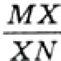 Review Questions for Chapter VI
 Topics: Natural resources of the Far East Protection of water resources of the country and our region