What are called absolute coordinates of points. Second Workshop - Supporting Elements
RELATIVE COORDINATE SYSTEM
When using flat processing, the technologist-programmer has the ability to set a relative coordinate system. The need for this very often arises, for example, in the case of mismatch between design and technological bases. To create a relative coordinate system, the user must use the command:
After calling the command, the following options will be available in the automenu:
Coordinate system parameters
Options with coordinate axes (, and) on their icons allow you to specify the center and corresponding axes of the coordinate system. As a rule, to specify each of these elements, a node is indicated in the part drawing.
The default parameter entry option allows the user to set all of the listed parameters with specific digital values in the “Coordinate System Parameters” dialog box.
To specify a relative coordinate system, it is enough to specify the center and one of the axes of the created coordinate system. After this, just use the button
The CNC will independently calculate the missing axis of the created coordinate system.
In order for the processing trajectory to be calculated in accordance with the created relative coordinate system, this coordinate system in the list of trajectories must be placed before the processing trajectory.

PROJECT SETUP
When using the T-FLEX CNC 2D version, the user can create processing paths and control programs based on them for different types processing (from electrical discharge to milling) on one drawing of the workpiece. For example, first the technologist-programmer does all the machining, and then the electrical erosion. The technologist-programmer makes all the necessary settings in the working project settings window that appears when calling the command:
In the example in the figure, there are two positions in the list of compound trajectories. “Machining 1” includes all drilling and milling of the workpiece. “Processing 2” is empty, but may include, for example, processing the part from the other side (for a different setup) or processing from the same side, but of a different type (electrical discharge or laser), or some other option.
[Add] and [Delete] keys
serve respectively to enter a new position into the list of composite trajectories or delete an old position.
It should be noted that for each position in the list of composite trajectories, its own control program is created in accordance with the postprocessor selected by the user.
Additionally, the constituent parts of an active compound toolpath are displayed in one color, while existing toolpaths are displayed in a different color.

Creating a control program
CREATION OF A CONTROL PROGRAM
After the technologist-programmer prepares a processing path in the system, he also needs to generate a control program for the machine used, with the postprocessor with which this machine works. To do this, in the case of 2D, 2.5D and 4D processing, use the command:
"CNC|Save G program"
For 3D and 5D processing paths:
When you call any of these commands, the “Save G Program” dialog box appears on the screen.
In the window that appears on the screen, you must
press , after which the “Parameters for saving a composite trajectory” dialog box will appear on the screen.
In this window, the names of the postprocessors required for the selected type of processing, the name of the control program and the location of its saving are sequentially specified.
It should be noted that the user can select postprocessors supplied with the system or those that were developed by him in the system using the postprocessor generator. The control program for the same part and for the same type of processing can be saved in different files with different post-processors. This makes it possible to optimally use equipment of the same type, but with different CNC stands.

If all the steps listed above were carried out correctly, the user will see a window on the screen that should contain all the entered data.
It should be especially noted that it is possible to remove a specific selected control program from the list. To do this, you need to specify it in the list using the or keys< >And< ↓ >, and then click the [Delete] button. It is also possible to save all control programs present in the list into separate files, for which you need to use the [Save] button.
Carrying out a flight along a given airway or route with the aim of bringing the aircraft to a given point or landing airfield requires the crew to have precise knowledge of the current location relative to the earth's surface. This requirement follows from the fact that the turning points of the flight route and the landing aerodrome are usually specified by geographical points, for example by names settlements or their geographical coordinates, which allow you to plot given line paths on the flight map or enter them into the programming device of the navigation complex.
Knowing the current position of the aircraft corresponding to a given moment in time, the crew can determine the correctness of the flight: whether the actual path line coincides with the given one. Correction of possible deviations is achieved by introducing corrections into the flight mode, i.e., adjusting the course and airspeed.
The aircraft's position can be obtained directly and indirectly. The direct determination of the MS is made by recording the moment the aircraft flies over an identified landmark and using technical means aircraft navigation. In the first case, as a rule, the moment when the plane is strictly above some landmark (object) is visually marked. This is the most reliable way to determine MS. However, it is extremely important to reliably identify the landmark here, since an error can lead to loss of orientation.
Direct determination of the MS using technical means of aircraft navigation is achieved by recording the moment of flight over a radar landmark or radio beacon. Indirect determination of MS is carried out by measuring some parameters, for example azimuth, range, altitude heavenly body etc., which are functionally dependent on the relative position of the aircraft and the external “source of navigation information. As a result of the measurement, the coordinates of the MS are obtained corresponding to the moment of determination, but most often in a coordinate system different from the one in which the path is monitored (reckoning They require further transformation. Ground-based radio beacons, visual and radar landmarks, and celestial bodies of natural and artificial origin are used as sources of positional information.
MS coordinates obtained on the basis of external information are called absolute, since they do not depend on navigation and flight modes, flight range and duration until the MS is determined. The accuracy of absolute coordinates is determined only by the means and conditions of measurement, as well as relative position aircraft and a source of positional information.
Currently, the following methods are used to determine absolute coordinates: by the moment of passage of a reference landmark; overview and comparative; coordinate transformations. Each of them has its own advantages and disadvantages, determined by the characteristics of the method itself and its technical implementation.
Continuous monitoring of the path during aircraft navigation is possible by two methods: determination of absolute coordinates or dead reckoning of the distance traveled.
The first method can be implemented if it is possible to continuously receive positional information from an external source. This can be achieved by using long-range radio navigation systems and satellite navigation systems that cover the entire intended flight area with their operating areas.
However, in most cases, measured absolute coordinates are used discretely, that is, at certain intervals. Therefore, for continuous aircraft navigation, the second method is implemented, which uses relative coordinates measured from the last MS obtained as a result of processing external information. Relative coordinates are determined by dead reckoning, based on the integration of the ground speed vector or aircraft acceleration over time. Consequently, this makes it possible to obtain not the MS coordinates themselves, but only their increment in time.
Dead reckoning allows you to determine MS coordinates relative to previously determined absolute ones. Thus, as a result of dead reckoning, the coordinates of the current MS are, as it were, “saved” in time and space between the moments of determining the absolute coordinates.
The main disadvantage of dead reckoning is that as soon as the number system is disrupted, for example, when the power supply to the navigation system fails, it is no longer possible to restore the current coordinates of the MS. To do this, it is necessary to determine absolute coordinates.
For dead reckoning, additional information about heading, aircraft speed and wind is used. The process of integration (summing) of the ground speed vector leads to the appearance of an increasing calculation error. Therefore, the accuracy of aircraft navigation largely depends on the duration of the flight in autonomous mode, during which the MS was not specified and its absolute coordinates were not determined. This reveals the connection and difference between relative and absolute coordinates. In principle, for reliable aircraft navigation, absolute coordinates contain enough navigational information, while the information contained in relative coordinates is quickly lost due to increasing dead reckoning errors.
Martynyuk V.A.
Second Workshop – Supporting Elements 1
Coordinate systems in NX 7.5 1
Working coordinate system 2
Orientation of RSK 3
When else do you need to remember about RSK 4?
Basic coordinate systems 4
How to recover a lost reference coordinate system 5
Concept of associativity 6
Auxiliary coordinate planes 8
Associated and fixed coordinate planes 9
Methods for constructing a coordinate plane 10
Auxiliary coordinate axes 11
Construction of perpendicular coordinate axes 12
Construction of points 14
The first method of constructing points is precise input 14
Constructing a point with an offset relative to another point 15
Constructing a point on face 15
Constructing a point on an auxiliary plane 16
Constructing point sets 17
Coordinate systems in Nx7.5
At the first seminar, we already mentioned that the NX7.5 system contains three coordinate systems:
Working coordinate system – (RSK).
Basic coordinate systems(there may be several of them).
Absolute coordinate system, which never changes its position. At the initial moment of working with a new project, all of the above coordinate systems coincide in place and in the orientation of the axes with the absolute coordinate system .

Fig.1 Fig.2
The very first thing you see on the screen in the workspace when you start a new project with the "Model" template- This:
Triad of vectors with a cube in the lower left corner of the screen (Fig. 1). It always shows the orientation of the axes absolute coordinate system in case your model rotates.
Two combined coordinate systems in the center (Fig. 2): RSK(colored arrows) and Basic coordinate system(brown arrows), which coincide with the absolute coordinate system. In Fig. 2 these two coordinate systems are combined. And herself absolute coordinate system considered invisible.
Working coordinate system
The working coordinate system (WCS) in the project is always the only one. But it can be arbitrarily moved in space. For what? The fact is that in NX7.5 there is a very important concept - working plane. This planeXOYworking coordinate system.
Why do we need the concept of a work plane? The fact is that in NX7.5, like in any other graphics system, there is flat construction apparatus . But if in other systems such a tool for flat constructions is onlyflat sketching , then in NX7.5, in addition to constructing flat sketches in the drop-down menu Insert\Curves There is a whole range of tools that can be used to direct drawing of flat primitives
without any mention of any sketches at all (Fig. 3). But these are flat primitives. This means they must be drawn in a plane! In what plane? Exactly!
in the working plane


Thus, if you want to somehow arbitrarily orient a flat ellipse in space, you will have to first orient the DCS and its working plane accordingly. And only then, in this working plane, build, for example, an ellipse (Fig. 4). Coordinates that indicate the location of a point, given the screen's coordinate system, are called absolute coordinates
. For example, PSET(100,120) means that a point will appear on the screen 100 pixels to the right and 120 pixels below the upper left corner, i.e. screen origin.
The coordinates of the point that was last drawn are stored in the computer's memory. This point is called the last reference point (LRP). For example, if, when drawing a line, you specify only the coordinates of one point, then a segment from the TPS to the specified point will be drawn on the screen, which will then itself become the TPS. Immediately after turning on graphics mode, the last link point is the point in the center of the screen. In addition to absolute coordinates, QBASIC also uses relative coordinates. These coordinates show the amount of movement of the TPS. To draw a new point using relative coordinates, you need to use keyword
STEP(X,Y), where X and Y are the coordinate offset relative to the TPS.
For example, PSET STEP(-5,10) - a point will appear whose position will be 5 points to the left and 10 points lower relative to the last reference point. That is, if the point of the last link had coordinates, for example, (100,100), then the result will be a point with coordinates (95,110).
Drawing lines and rectangles.- draws a segment connecting points (X1,Y1) and (X2,Y2), color C.
For example, LINE(5,5)-(10,20),4
Result: 5 10
If you do not specify the first coordinate, then a segment will be drawn from the TPS to the point with coordinates (X2, Y2).
LINE(X1,Y1)-(X2,Y2), C, V- draws the outline of a rectangle with the ends of the diagonal at points (X1, Y1) and (X2, Y2), C - color, B - rectangle marker.
For example, LINE(5,5)-(20,20), 5, V
Result: 5 20

If instead of marker B you specify BF, then a filled rectangle (block) will be drawn:
LINE(X1,Y1)-(X2,Y2),C, BF
For example, LINE(5,5)-(20,20),5, BF
 Result: 5 20
Drawing circles, ellipses and arcs.
CIRCLE(X,Y), R, C- draws a circle with center at point (X,Y), radius R, color C.
For example, CIRCLE(50,50), 10, 7
Result:
 50
50
CIRCLE(X,Y), R, C, f1, f2- arc of a circle, f1 and f2 arc angle values in radians from 0 to 6.2831, defining the beginning and end of the arc.
CIRCLE(X,Y), R, C, e- ellipse, with center at point (X, Y), radius R, e - the ratio of the vertical axis to the horizontal.
For example, CIRCLE(50,50), 20, 15, 7, 1/2
Result: 30 50 70

If necessary, after parameter C you can specify the values of the ellipse arc angles f1 and f2.
PAINT(X,Y), C, K- paint over the figure drawn with color K with color C, (X,Y) - a point lying inside the figure. If the outline color matches the fill color, then only one color is indicated: PAINT(X,Y), C
For example, you need to paint the circle CIRCLE(150,50), 40, 5 with color 4. To do this, you need to execute the statement PAINT(150,50), 4, 5 , because The center of the circle lies exactly inside the shape being shaded, we used it as an internal point.
Problem solving.
Task 1.
Draw four points that lie on the same horizontal line at a distance of 20 pixels from each other. The last reference point has coordinate (15, 20).
Solution: NOTES.
SCREEN 9: COLOR 5.15:REM graphic. mode, background 5, color 15
CLS:REM screen clearing
PSET(15,20) :REM draws a point with coordinates (15,20)
PSET STEP(20,0) :REM draws a point with an offset
PSET STEP(20,0) :REM relative to the last one by 20
PSET STEP(20,0) :REM pixels along the OX axis.
Result: 15 35 55 75

20. . . .
Task 2.
Draw three circles, the centers of which lie on the same horizontal line at a distance of 30 pixels from each other. The radii of the circles are 20, the center of the first circle coincides with the center of the screen.
Solution.
 SCREEN 9 120 150 180
CIRCLE STEP(0, 0), 20, 15 100
CIRCLE STEP(30, 0), 20, 15
CIRCLE STEP(30, 0), 20, 15
Task 2.
Construct a quadrilateral with vertices (10,15), (30,25), (30,5) and (20,0).
LINE (10,15)-(30,25), 5
LINE - (30, 5),5
LINE - (25.0), 5
LINE - (10,15), 5
RESULT: 5 10 20 25 30
 15
15
Write a program to draw an arbitrary picture.
Helpful advice: Before you start writing a program, draw a picture on a squared piece of paper and place the required coordinates. You will immediately see which numbers will be used as operands in your program.
To solve most problems in applied sciences, it is necessary to know the location of an object or point, which is determined using one of the accepted coordinate systems. In addition, there are height systems that also determine the altitude location of a point on
What are coordinates
Coordinates are numerical or alphabetic values that can be used to determine the location of a point on the ground. As a consequence, a coordinate system is a set of values of the same type that have the same principle for finding a point or object.
Finding the location of a point is required to solve many practical problems. In a science such as geodesy, determining the location of a point in a given space is the main goal, on the achievement of which all subsequent work is based.
Most coordinate systems typically define the location of a point on a plane limited by only two axes. In order to determine the position of a point in three-dimensional space, a height system is also used. With its help you can find out the exact location of the desired object.
Briefly about coordinate systems used in geodesy
Coordinate systems determine the location of a point on a territory by giving it three values. The principles of their calculation are different for each coordinate system.

The main spatial coordinate systems used in geodesy:
- Geodetic.
- Geographical.
- Polar.
- Rectangular.
- Zonal Gauss-Kruger coordinates.
All systems have their own starting point, values for the location of the object and area of application.
Geodetic coordinates
The main figure used to measure geodetic coordinates is the earth's ellipsoid.
An ellipsoid is a three-dimensional compressed figure that best represents the shape of the globe. Due to the fact that the globe is a mathematically irregular figure, an ellipsoid is used instead to determine geodetic coordinates. This makes it easier to carry out many calculations to determine the position of a body on the surface.

Geodetic coordinates are defined by three values: geodetic latitude, longitude, and altitude.
- Geodetic latitude is an angle whose beginning lies on the plane of the equator, and its end lies at the perpendicular drawn to the desired point.
- Geodetic longitude is the angle measured from the prime meridian to the meridian on which the desired point is located.
- Geodetic height is the value of the normal drawn to the surface of the Earth's ellipsoid of rotation from a given point.
Geographical coordinates
To solve high-precision problems of higher geodesy, it is necessary to distinguish between geodetic and geographic coordinates. In the system used in engineering geodesy, such differences are usually not made due to the small space covered by the work.
To determine geodetic coordinates, an ellipsoid is used as a reference plane, and a geoid is used to determine geographic coordinates. The geoid is a mathematically irregular figure that is closer to the actual shape of the Earth. Its leveled surface is taken to be that which continues under sea level in its calm state.

The geographic coordinate system used in geodesy describes the position of a point in space with three values. longitude coincides with the geodetic, since the reference point will also be called Greenwich. It passes through the observatory of the same name in London. determined from the equator drawn on the surface of the geoid.
Height in the local coordinate system used in geodesy is measured from sea level in its calm state. On the territory of Russia and the countries of the former Union, the mark from which heights are determined is the Kronstadt footpole. It is located at the level of the Baltic Sea.
Polar coordinates
The polar coordinate system used in geodesy has other nuances of making measurements. It is used over small areas of terrain to determine the relative location of a point. The origin can be any object marked as the initial one. Thus, using polar coordinates it is impossible to determine the unambiguous location of a point on the territory of the globe.

Polar coordinates are determined by two quantities: angle and distance. The angle is measured from the northern direction of the meridian to a given point, determining its position in space. But one angle will not be enough, so a radius vector is introduced - the distance from the standing point to the desired object. Using these two parameters, you can determine the location of the point in the local system.
As a rule, this coordinate system is used to perform engineering work carried out on a small area of terrain.
Rectangular coordinates
The rectangular coordinate system used in geodesy is also used in small areas of terrain. The main element of the system is the coordinate axis from which the counting occurs. The coordinates of a point are found as the length of perpendiculars drawn from the abscissa and ordinate axes to the desired point.

The northern direction of the X-axis and the eastern direction of the Y-axis are considered positive, and the southern and western directions are considered negative. Depending on the signs and quarters, the location of a point in space is determined.
Gauss-Kruger coordinates
The Gauss-Kruger coordinate zonal system is similar to the rectangular one. The difference is that it can be applied to the entire globe, not just small areas.
The rectangular coordinates of the Gauss-Kruger zones are essentially a projection of the globe onto a plane. It arose for practical purposes to depict large areas of the Earth on paper. Distortions arising during transfer are considered to be insignificant.
According to this system, the globe is divided by longitude into six-degree zones with an axial meridian in the middle. The equator is in the center along a horizontal line. As a result, there are 60 such zones.

Each of the sixty zones has its own system of rectangular coordinates, measured along the ordinate axis from X, and along the abscissa axis from the section of the earth's equator Y. To unambiguously determine the location on the territory of the entire globe, the zone number is placed in front of the X and Y values.
The X-axis values on the territory of Russia, as a rule, are positive, while the Y values can be negative. In order to avoid a minus sign in the x-axis values, the axial meridian of each zone is conditionally moved 500 meters to the west. Then all coordinates become positive.
The coordinate system was proposed as a possibility by Gauss and calculated mathematically by Kruger in the mid-twentieth century. Since then it has been used in geodesy as one of the main ones.
Height system
Coordinate and elevation systems used in geodesy are used to accurately determine the position of a point on the Earth. Absolute heights are measured from sea level or other surface taken as the source. In addition, there are relative heights. The latter are counted as the excess from the desired point to any other. They are convenient to use for working in a local coordinate system in order to simplify subsequent processing of the results.
Application of coordinate systems in geodesy
In addition to the above, there are other coordinate systems used in geodesy. Each of them has its own advantages and disadvantages. There are also areas of work for which one or another method of determining location is relevant.
It is the purpose of the work that determines which coordinate systems used in geodesy are best used. To work in small areas, it is convenient to use rectangular and polar coordinate systems, but to solve large-scale problems, systems are needed that allow covering the entire territory of the earth's surface.
 Diophantine equation: solution methods with examples
 Verb "to be" Je suis conjugation
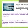 Physics presentation "sound waves"